Types of 5.08mm Pitch Pluggable PCB Terminal Blocks

Introduce you to the various types of 5.08mm pitch pluggable PCB terminal blocks that we offer. There are a total of six different types available:

1. Open straight pin PCB terminal block: This type features hollow sides in the plastic housing for easy customization of PCB length requirements. The pins are straight at 180 degrees for easy insertion.

2. Open right-angle pin PCB terminal block: Similar to the straight pin type, but with right-angle pins at 90 degrees for different PCB design needs.

3. Closed straight pin PCB terminal block: This type features plastic housing on both sides of the pins for added stability. The pins are straight at 180 degrees.

4. Closed right-angle pin PCB terminal block: Similar to the closed straight pin type, but with right-angle pins at 90 degrees for specific design requirements.

5. Flanged straight pin PCB terminal block: This type features additional flanges on both sides of the closed pins, with copper nuts inside the flanges for enhanced stability during insertion and removal. The pins are straight at 180 degrees.

6. Flanged right-angle pin PCB terminal block: Similar to the flanged straight pin type, but with right-angle pins at 90 degrees for specific design applications.

READ MORE >

What are pluggable terminal blocks?

 This terminal block is primarily comprised of a male header and a female socket, allowing for easy and secure connection of wires and cables.One of the key features of our Pluggable Terminal Block is its versatility in terms of spacing options. We offer a variety of standard spacing options, including 3.5mm, 3.81mm, 5.0mm, 5.08mm, 7.5mm, and 7.62mm. This allows for greater flexibility in designing and customizing your electrical connections.Pluggable Terminal Block is an electrical connection device specially designed for easy connection and removal of wires. They are usually made of insulating materials and have a pluggable wire connection function, which is used to safely connect wires to circuit boards or other electronic devices.


Pluggable terminal blocks have the following main features and advantages:

1. Plug-in connection: Pluggable terminal blocks allow users to easily insert and remove wires. They usually have a spring-type or screw-type wire connection mechanism, making the connection and removal process simpler and faster. In this way, when maintenance, replacement or repair is required, the wire can be easily removed and replaced without intervening in the entire circuit or equipment.


2. Flexibility and adjustability: Pluggable terminal blocks provide flexible wire connection methods. They usually have adjustable sockets or wiring screws that can be adjusted according to wire size or demand, suitable for wire connections of different specifications.


3. Maintenance and troubleshooting: Pluggable terminal blocks play an important role in the maintenance and troubleshooting process. Through plug-in connection, it is more convenient to check, replace or repair wires without disassembling a large number of circuit boards or equipment.


4. Identification and management: Pluggable terminal blocks usually have an identification area for marking the wires or circuits connected to each terminal block. This helps to identify and manage the connections of the circuits and improve the efficiency of maintenance and troubleshooting.


5. Reliability and safety: Pluggable terminal blocks provide reliable electrical connections and have good insulation properties. They ensure the stability and safety of the wires during the connection process, reducing the risk of wiring errors and circuit failures.


In short, pluggable terminal blocks provide a convenient, flexible and fast way to connect and remove wires. They are suitable for a variety of electronic devices and circuit boards, and provide convenience and reliability during maintenance, replacement and troubleshooting.

Our Pluggable Terminal Block is designed to be user-friendly and durable, ensuring a reliable and long-lasting connection for your applications. The easy plug-and-play design makes installation and maintenance a breeze, saving you time and effort.

Whether you are working on a large-scale industrial project or a small-scale DIY project, our Pluggable Terminal Block is the ideal solution for your wiring needs.

READ MORE >

What is a terminal on a circuit board?

On a circuit board, terminals are metal pins or sockets for electronic components or wires. They serve as connection points and provide physical and electrical connections between electronic components and circuit boards. Here are some common types of terminals on circuit boards:


1. Socket terminals: Socket terminals are usually holes or slots made of metal for inserting pins of electronic components (such as diodes, resistors, integrated circuits, etc.). Socket terminals can provide stable and reliable connections, facilitating the plugging and unplugging and replacement of components.


2. Pin terminals: Pin terminals are metal pins of the electronic components themselves, which are connected by welding or inserting into holes on the circuit board. They can be in different forms such as straight-in pins, surface-mount pins, package pins, etc., used to connect electronic components to circuit boards.


3. Stud terminals: Stud terminals are usually used to connect high-power components or wires, such as motors, power supplies, resistors, etc. They usually have a threaded structure, and the wires are clamped and an electrical connection is established by tightening the nut.


4. Spring contact terminals: Spring contact terminals use spring force to provide a tight connection. They are usually used in occasions that require frequent plugging and unplugging, such as test points or connecting external devices.


5. Blade terminals: Blade terminals are similar to socket terminals, but are usually used for high current applications. They have blade-shaped pins that can quickly connect electronic components by plugging and unplugging.

 Our team has extensively tested and evaluated the Homnecks connector terminals and we are pleased to report that they have displayed excellent performance and reliability. The terminals have shown exceptional conductivity and durability, ensuring secure and stable connections on the PCB boards.


Furthermore, the use of
Homnecks connector terminals has proven to be incredibly efficient and user-friendly. The terminals are easy to install and provide a secure connection without the need for additional tools or complicated processes. This not only saves time during assembly but also reduces the risk of errors or malfunctions.

The function of the terminal is to provide a reliable electrical connection on the circuit board, allowing electronic components to pass current and signals to and from the circuit board. They allow for assembly, maintenance and testing of circuit boards, and provide flexibility and convenience. Different types of terminals are suitable for different connection needs and are selected according to the specific application and component type.


READ MORE >

What is PCB terminal block?

PCB terminal block refer to electrical connection devices for connecting on printed circuit boards (PCBs). They provide a reliable and convenient way to connect and disconnect circuits, and are usually used to fix wires or connect plugs, sockets and other devices.


There are many types of PCB terminals, the most common of which include:


1. Pluggable terminal block:The Pluggable PCB Terminal Blocks are available in different configurations to suit your specific needs. The main types include male parts and female parts, with standard pin spacings of 2.5mm, 3.5mm, 3.81mm, 5.0mm, 5.08mm, 7.5mm, and 7.62mm. Homnecks provide flexibility for various design requirements and compatibility with different systems.


2.Screw terminal block: a convenient and efficient solution for your PCB assembly needs. Our Screw Terminal Block can be directly soldered onto your PCB board, allowing for easy and secure wire connections. The screw terminals provide a reliable and secure connection that can easily be loosened or tightened for quick and convenient wire adjustments.


3. Barrier  terminal block: PCB Barrier Terminal Block, designed for high-performance controller products that require superior electrical properties.

Featuring a plastic material made of flame-retardant PA66 and tin-plated copper metal components, our Barrier Terminal Block offers excellent electrical performance. This makes it ideal for applications where high current and voltage requirements are a priority.

4.Spring Terminal: Spring terminals use spring mechanisms to achieve circuit connection by clamping wires or terminal pins. This type of terminal usually has the characteristics of quick connection and disconnection, which is convenient for maintenance and replacement.


Our terminal blocks are manufactured with high-quality materials to ensure reliable performance and durability. They are designed for easy installation and maintenance, making them ideal for a wide range of industrial and commercial applications.

READ MORE >

What is the function of terminal block?

Terminal blocks are electrical connection devices used to safely connect wires in a circuit together or to electrical equipment. They are usually made of insulating materials and have conductive connection points for inserting or connecting wires.


Homnecks Terminal blocks have the following main functions:

1. Homnecks Terminal blocks can make wire connection: Terminal blocks provide a safe and reliable connection point for wires. Wires can be connected to terminal blocks by insertion, crimping or threading. This makes it easier to maintain and replace wires when they need to be connected or disconnected without directly affecting the entire circuit.


2. Homnecks Terminal blocks can make line distribution: Terminal blocks are often used to distribute current from one circuit to multiple branch circuits. By connecting different wires to terminal blocks, current can be divided and distributed, making circuit design more flexible and variable.


3.  Homnecks Terminal blocks can Insulation and protection: Terminal blocks are usually made of insulating materials and can provide electrical isolation and protection. This prevents problems such as short circuits and electric shocks between wires and reduces accidental risks.


4. Homnecks Terminal blocks can  Identification and management: Terminal blocks usually have identification areas to mark the wires or circuits connected to each terminal block. This helps identify and manage circuit connections and improves the efficiency of maintenance and troubleshooting.

We are confident that our Homnecks Terminal Block will enhance the functionality and efficiency of your controller products. If you have any questions or would like to learn more about our product, please do not hesitate to contact us. We look forward to the opportunity to collaborate with you on your upcoming projects.

READ MORE >

When it comes to high-quality terminal blocks, there are several key factors that must be considered in order to ensure optimal performance and reliability.

First and foremost, the materials used in the terminal blocks play a crucial role in their overall quality. The insulation housing should be made of flame-retardant engineering plastic, while the conductive components should be made of copper alloy materials. This is because the plastic insulation material and the conductive components directly influence the quality of the terminal block, determining its insulation and conductivity functions.

In addition, the production process of the terminal blocks is also critical. If the production process is not up to standard, the thread processing is not done properly, and the torque is not within specifications, the terminal block will lose its ability to connect wires effectively.

Furthermore, the appearance of the terminal blocks is also important. A high-quality terminal block should not only meet the functional requirements, but also have a visually appealing appearance. A well-designed terminal block can make a positive impression on users and enhance the overall user experience.

In conclusion, when it comes to high-quality terminal blocks, it is essential to consider the materials used, the production process, and the overall design of the product in order to ensure optimal performance and reliability.

READ MORE >

When using PCB terminal blocks for wiring applications, it is important to keep in mind the following precautions.

When using PCB terminal blocks for wiring applications, it is important to keep in mind the following precautions:

1. Always ensure that the power is switched off before starting any wiring operations. Never attempt to work on the terminal blocks while they are live. If you are unsure whether the power is off, use a voltage tester to verify. Additionally, if there are sliding buttons on the terminal blocks or switches, it is advisable to replace them if they are worn out to prevent any risk of electric shock.

2. When connecting to the power source, make sure to install PVC conduit for wire routing. Avoid leaving wires hanging loosely without any proper support or fixation on support brackets or busbars.

3. Pay attention to the length of the wires when connecting to the switch box. It is recommended to keep the wire lengths within a suitable range and properly route them through conduits. Avoid pushing the wires directly into the switches for fixing.

By following these precautions, you can ensure safe and efficient operation of the PCB terminal blocks. If you have any further questions or need assistance, please feel free to contact us.

READ MORE >

Crimping performance analysis of high voltage terminal in automotive high voltage wire harness High voltage wire harness is an important carrier of the power and signal transmission and distribution

High voltage wire harness is an important carrier of the power and signal transmission and distribution system of new energy vehicles, and the crimping performance of high voltage wire harness terminals is the most important performance index of new energy vehicles. This paper establishes a data analysis model for the crimping performance of high voltage wire harness terminals of new energy vehicles, and finds out the best adaptation range of the compression ratio of high voltage wire harness terminals by analyzing relevant data, so as to improve the process capability and quality level of high voltage wire harness cold crimping.

With the rapid advancement of the country's new energy automobile industry, it has brought major opportunities to the development of new energy wiring harnesses. The difference between high-voltage wire harness and low-voltage wire harness terminals is that high-voltage terminals tend to generate heat due to the large current passing through them, which leads to the decrease of terminal mechanical strength and wire harness insulation performance, and causes conductor oxidation to further aggravate heat and other problems. High voltage terminal crimping needs to consider not only the reliability of crimping, but also the low temperature rise at the crimping area. This paper mainly studies the effect of cold crimping on terminal temperature rise.


01 Crimp type

High voltage terminals are commonly connected by crimping, resistance welding, and high frequency welding. Crimping equipment and dies are used to connect wires and terminals together through a crimping process. High-frequency welding is the use of high-frequency welding machine wire and terminal welding together. Resistance welding is the use of special resistance welding equipment to connect wires and terminals together.

This paper mainly analyzes the performance of crimping. The advantages of ordinary crimping: simple operation, easy use and maintenance, low manufacturing cost, high operational efficiency, suitable for mass production. Disadvantages: The wiring harness and terminals that require high current pass rate and small resistance after the connector requires the wire and terminal to be connected cannot be met.

The common crimping mode of the large square high voltage terminal is shown in Figure 1, which is a hexagonal closed terminal. The advantages of ordinary crimping are obvious, but it is particularly important to minimize the resistance of ordinary crimping. Reducing resistance means reducing heat, reducing product temperature rise, and making product life and quality better.


02 terminal heating hazards

After the terminal is heated, it is easy to oxidize itself and the contact surface of the conductor, forming an oxide film, which increases the contact resistance, and the increasing speed increases exponentially with the increase of temperature, further increasing the temperature rise speed of the terminal, which will cause a fire in serious cases. At the same time, the elastic element of the contact structure will be annealed, the contact pressure will be reduced, and the contact resistance will be further increased. In addition, the heat will make the insulation layer of the wire connecting the terminal aging brittle, causing the insulation performance to decline, there is a risk of leakage overheating caused by fire.


03 Heat source of terminal

As shown in Figure 2, the high voltage harness has three heat sources.

3.1 Conductor

The conductor itself has resistance, the smaller the cross-sectional area, the higher the resistance, and the resistance will cause heating.

3.2 Terminal crimping

If the compression ratio is not enough, the conductor will be loose, resulting in large resistance and easy heating. Excessive crimping is easy to cause the cross-sectional area to become smaller, and the carrying current is not enough to cause heat.

3.3 Contact of male and female terminals

The terminal contact is poor, or the contact surface of the terminal is oxidized, resulting in serious heating.


04 Method to reduce the terminal temperature

4.1 Reduce contact resistance

(1) Materials with low resistivity are used. Commonly used high-voltage terminals are H62, H65 copper, or high-conductivity copper. For products larger than 125 A, it is recommended to use high-conductivity copper with low resistivity.

(2) Reduce the contact resistance of the conductor. Compact the terminal and conductor as much as possible to reduce the crimping resistance.

(3) Increase the cross-sectional area of the conductor, increase the cross-sectional area, and reduce the temperature rise of the wire.

4.2 Increase the heating area of the conductor

(1) Forced cooling, air cooling, water cooling and other measures can be used.

(2) Reasonable arrangement of conductors, wiring harnesses with large current, as far as possible arranged in a space that is easy to dissipate heat, conducive to natural heat dissipation.


05 Effect of crimping on temperature rise

For crimping, refer to the 4.2.6 voltage drop test requirements in QC/T 29106-2014 "Automotive Wiring Harness Technical Conditions" [1] and the temperature rise test requirements in GB/T 20234.1-2015 "Connection Devices for conductive Charging of electric vehicles Part 1 General Requirements" for verification. The process is shown in FIG. 3 and FIG. 4. The obtained data are shown in Table 1.


5.1 Compression ratio/Compression ratio calculation method

(1) Refer to VW60330-2013 standard

Where, Acrimp is the cross-sectional area of the conductor contained in the crimp; Aconductor is the nominal cross-sectional area of the conductor.

(2) Refer to SAE/ USCAR21-2014 standards

Where, T is the area retained when the crimp blade is closed; At is the cross-sectional area of the nominal terminal; Ac is the cross-sectional area of the nominal conductor.

(3) The difference between conductor compression ratio and terminal compression ratio

According to VW 60330-2013 [4] standard, the calculation of compression ratio only includes the compression of the conductor without the terminal, which can directly reflect whether the conductor has a gap. When the compression ratio is less than 100%, there should be no gap. We can call it the wire compression ratio.

According to the SAE/ USCAR21-2014 standard, the calculation of the compression ratio includes the compression of the conductor and the terminal, which cannot directly reflect whether there is a gap in the conductor, but can directly reflect the real cross-sectional area of the compression joint. In order to facilitate data comparison, this article defines the terminal compression ratio =100T/ (At+Ac).

Both calculation methods have their own advantages.


5.2 Analysis Results

(1) As shown in Table 1, when the conductor compression ratio of product 3# reaches 104%, the pulling force has reached the standard of 50 mm2 stipulated in QC/T 29106-2014, and the conductor pulling force is ≥2 700 N, but at this time, the compression joint has not been fully compacted, and there are large safety risks. Therefore, the tension of the high voltage terminal can not be used as a standard to judge the quality.

(2) The resistance value in the table is not completely corresponding to the temperature rise trend, which should be caused by the difference in the contact resistance of the terminal individual and the inconsistency caused by the oxidation of the terminal coating. However, from the general trend, it basically conforms to the corresponding relationship of lower resistance and lower temperature.

(3) The compression ratio of the 7# terminal is 73%, and there is an oxide layer on the surface of the conductor and the terminal, which will gradually be destroyed with the reduction of the compression ratio value. When the compression ratio of the terminal is 73%, the oxide layer of the conductor begins to collapse, which makes the copper wire fuse more tightly and the temperature rise is slightly reduced, indicating that the terminal compression comparison is appropriate at this time.

(4) From the point of view of temperature rise value fluctuation, the impact of crimping on temperature rise can reach 10 ℃. This has a greater impact on the crimping of high voltage terminals.

(5) 10# Product terminal compression ratio At 60%, the theoretical cross-sectional area of the conductor at the terminal crimp is only 30 mm2, according to SAE/ USCAR21-2014 terminal compression ratio calculation, the cross-sectional area at the crimp in addition to the conductor, the cross-sectional area of the terminal should also be included. The actual cross-sectional area between the crimped conductor and the terminal is 66.97 mm2, which is greater than the nominal cross-sectional area of the conductor of 50 mm2. Therefore, the compression ratio does not cause a bottleneck at the compression area, and is in line with the actual situation. In addition, the calculation method of the terminal compression ratio is more suitable for high-voltage terminals.

(6) Too low compression ratio will cause the temperature rise at the crimp joint to be too high. According to the actual measurement, when the terminal compression ratio reaches below 40%, the terminal crimp resistance will gradually increase. The terminal temperature rise began to rise slightly.

(7) Terminal compression ratio analysis for hexagonal crimp terminals. First of all, no matter what the cross-sectional area of the pressure junction should not be less than the nominal conductor cross-sectional area; Secondly, due to the material thickness selection of each high-voltage terminal will be different, according to the terminal compression ratio =100T/(At+Ac), some terminals have a low At cross-sectional area, after compression, too low terminal compression ratio will cause the cross-sectional area of the crimp is less than the nominal conductor cross-sectional area. Therefore, the cross-sectional area after crimping needs to be as large as possible. In addition, if the compression ratio is too low, the mechanical tension value of the terminal will decrease, which will affect the reliability of the terminal crimping.


06 Conclusion

Based on the above analysis, consider the reliability of terminal crimping strength and terminal resistance. The actual terminal compression ratio is controlled at 65% ~ 75%, and the conductor compression ratio is 65% ~ 80%. In addition, from the experimental data, some of the resistance and temperature rise data fluctuations are related to the coating and oxidation of the terminal and the contact structure of the terminal, so it is not enough to reduce the temperature rise from the perspective of crimping quality alone. It is necessary to pay special attention to the daily preservation of the terminals, the quality of the coating of the terminals, and the life of the terminals, the insertion force, and the contact area.

For products with large temperature rise, it is recommended to use high-frequency welding, which makes copper heat through friction at ultra-high frequencies, melting copper and bonding, which has lower resistance, so it has a better effect in controlling temperature rise.

Aichie Tech provides auto wiring harness , high voltage ev cable assembly and low -voltage auto wiring harness around the world. It has introduced new production equipment, which greatly improves the quality and efficiency of production. Customers are widely distributed in Europe and North America. Production employees and experienced engineering teams and sales teams serve our customers; please contact us now! We will provide you with competitive prices!

E: sales03@aichie.com

WeChat: 180 2750 2150

Tel: +86 180 2750 2150

READ MORE >

High voltage wire harness cost reduction method

At present, the competition in the new energy vehicle market is becoming increasingly fierce. With Tesla's price reduction, BYD's open letter asking suppliers to reduce prices and other events, it can be expected that the subsequent competition will enter a more heated stage.

If automobile companies want to win a place in the highly competitive new energy vehicle market, they can only rely on high-quality products with high added value and leading technology. While the major car companies continue to promote technological innovation, they also focus on the optimization of parts costs in order to enhance product strength and enhance the competitiveness of enterprises. Among them, high-voltage wiring harnesses, as highly valuable components in pure electric vehicles, naturally become the key to cost optimization.

1. Introduction to high voltage wiring harness

The high voltage wiring harness connects the various components of the high voltage system, as the medium of high voltage power transmission, and is the main carrier of power output on the electric vehicle, mainly used for transmitting electric energy and shielding external signal interference.

High voltage harness has the characteristics of high voltage, high current, high protection level and anti-electromagnetic interference, which is the neural network of pure electric vehicle high voltage system, and is the key component of vehicle performance and safety.

High voltage wiring harnesses of pure electric vehicles are generally divided into power battery high voltage wiring harnesses, motor controller high voltage wiring harnesses, fast charging socket wiring harnesses, slow charging socket wiring harnesses, air conditioning system wiring harnesses and charging high voltage wiring harnesses, among which charging high voltage wiring harnesses are the wiring harnesses connecting high voltage distribution boxes to vehicle chargers, air conditioning compressors and power battery pack heaters.

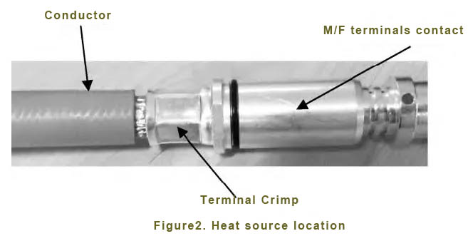
The high-voltage wire harness mainly consists of high-voltage connectors, high-voltage cables, cladding materials (tape, heat shrink pipe, bellows, wear-resistant self-winding pipe, etc.), and protection plates. The production process of high voltage wire harness mainly includes cutting wire, preassembly of accessories, terminal crimping/ultrasonic welding, shielding crimping, wire harness assembly and electrical inspection.

2. Cost composition of high voltage wiring harness

The cost of high voltage wiring harness consists of material cost, processing fee, packaging and transportation fee and management fee.

The material cost of high voltage wiring harness is mainly determined by the technical scheme of wiring harness, and the processing cost includes labor cost, power cost, equipment depreciation cost and low value consumable goods.

The following is the cost composition ratio of the high-voltage wiring harness of a certain vehicle (see Figure 1) and the cost composition ratio of the high-voltage wiring harness material (see Figure 2). The cost of the high-voltage wiring harness material accounts for about 73.8% of the total cost of the wiring harness. It is necessary to reduce the cost of high voltage wiring harness by optimizing design and production process.

Figure 1 Proportion of the cost composition of high voltage wiring harness Figure 2. Material cost composition ratio of high voltage wiring harness


3 High voltage wire harness cost reduction research

There are three main methods to reduce the cost of enterprises in the automotive industry, including scale, supplier collaboration and technology cost reduction, among which technology cost reduction is the most effective and sustainable way to reduce costs.

At present, there are three main methods of cost reduction: cost benchmarking, management technology and technical means.

Under normal circumstances, the method of technical means includes reducing redundant functions, improving the localization rate and standardizing the platform.

In the pure electric vehicle high voltage wiring harness cost reduction activities, this research mainly uses technical means to optimize the cost of high voltage wiring harness from the following aspects.

3.1 High-voltage system architecture optimization

On pure electric vehicles, High-voltage components include power battery, 3-in-1 (motor controller + drive motor + subtraction), PDU (high-voltage distribution box), ECP (electric compressor), 2-in-1 (IPS=OBC+DC-DC), HVH (battery heating), PTC (occupant heating), slow charger (ACInlet), and fast charger (DC) Inlet, high pressure harness, etc. These components constitute the high pressure system of the vehicle. The high voltage system architecture of pure electric vehicles is optimized, which can greatly reduce the number of connectors used and redundant high voltage wiring harnesses. Taking the high voltage system architecture optimization of a project as an example, before optimization, PDUs in the high voltage wiring harness system architecture only exist as power distribution function modules, and there is no vehicle functional performance related module, as shown in Figure 3.

FIG. 3 Architecture diagram of high voltage system before optimization

The independence of PDUs increases the number of transfers in HV wiring harness systems. The two functions of HVH and PTC are similar, resulting in an increase in the number of high-voltage harness circuits. The fast and slow charging sockets are arranged on the left and right rear side, and are too far away from the electrical interface (the battery fast charging interface is in the front, and the charger slow charging interface is in the front cabin), so that the high voltage wiring harness length is too long.

After research and analysis, the functional electrical components are only used for connecting the function of copper bar and power protection function of the fuse, and it is easy to integrate with other electrical appliances. The PDU and IPU integration can eliminate a high voltage distribution box assembly, while saving a set of motor controller wiring harnesses (approximately 1.5m of 50mm2 wire and two pairs of φ8mm terminal connectors), which can bring significant cost reduction. HVH and PTC have similar functions, and when the two functions are combined, the high-voltage wiring harness can reduce one loop (about 1.5m of 3mm2 wire and two pairs of 2.8mm blade width terminal connectors), and the high-voltage system architecture is optimized, as shown in Figure 4.

FIG. 4 Architecture diagram of high voltage system after optimization

Through this high voltage system architecture optimization, four high voltage connectors and two high voltage wiring harnesses are reduced, and the cost of high voltage wiring harnesses can be reduced by about 730 yuan.

3.2 Optimization of high-voltage wiring harness layout

The high-voltage wiring harness layout needs to be continuously optimized according to the model, and the use of high-voltage cables can be reduced after optimization to further reduce costs. Taking the layout optimization of the fast and slow charging ports of a certain vehicle as an example, before optimization, the fast and slow charging ports were arranged in the left and right rear side, and the length of the fast and slow charging harnesses was too long, among which the length of the slow charging harnesses was about 4.5m and the length of the fast charging harnesses was about 4m, resulting in high cost of the fast and slow charging high-voltage harnesses. After optimization, the charging port is arranged at the left and right sub-boards, close to the charger and battery pack, to reduce the length of high voltage wiring harness. The layout diagram before and after optimization is shown in Figure 5 and 6. The cost can be reduced by about 260 yuan through this high-voltage wiring harness layout optimization.

Figure 5 Layout diagram of fast and slow charging before optimization

Figure 6 Layout diagram of fast and slow charging after optimization

3.3 High voltage harness material optimization

High voltage wire harness cost composition, material cost accounted for the highest, the current status of the analysis, the current high voltage wire harness material optimization direction mainly for charging socket integrated design, high voltage connector localization, high voltage cable diameter optimization and material one-to-many optional optimization.

3.4 Integrated design optimization of charging socket

Before optimization, the charging socket is designed as a split type with high cost. Before optimization, the split type charging socket is shown in Figure 7, including a fast charging socket and a slow charging socket. Through the development and design of the charging socket according to the platform scheme, the main structure of the charging socket of all projects is solidified to minimize the development cost. After optimization, the integrated charging socket is shown in Figure 8. Through this optimization, a set of flange molds can be reduced and the high voltage wiring harness assembly cost can be reduced by about 8 yuan.

Figure 7 Split charging socket before optimization

Figure 8 Integrated charging socket after optimization

3.5 High voltage connector localization

In recent years, the high voltage connector industry has developed rapidly, and a number of excellent domestic high voltage connector brand suppliers have emerged. Before optimization, the main use of TE and other foreign brands of high-voltage connectors, through the localization of high-voltage connectors continuous optimization, with domestic brands such as Luxshare, Ebusbar and other localization replacement, the cost reduction of high-voltage connectors is of great significance, as shown in Table 1 below for the high-voltage connector localization demonstration case.

Table 1 High-voltage connector localization demonstration case

Original Brand Original P/N Equivalent Brand Equivalent P/N
TE 1-2347299-1 Ebusbar 123-0500-0002
TE 2-2356258-2 Luxshare HVP800022CVA11

3.6 High voltage cable diameter optimization

Through the interpretation of regulations, benchmarking and statistical cloud big data measures to optimize the cable diameter of high voltage lines. For specific high-voltage cables, it is often possible to optimize the section, temperature requirements, flexibility and shielding effect to avoid excessive size and excessive components. Taking fast-charging high-voltage cables as an example, the optimized front-line cable diameter is 70mm2, and the optimized cable diameter is 50mm2, which can meet the actual charging requirements.

3.7 One-to-many optional optimization of materials

The one-to-many high-voltage wiring harness materials can fully mobilize the enthusiasm of tier1 suppliers and make use of tier1 suppliers' own supply chain advantages to choose the best cost plan for supply. Taking high-voltage cables with relatively high material costs as an example, the current main specifications of high-voltage cables are developed according to the one-to-many idea according to the high-voltage cable standard, and each specification harness factory has multiple specifications to choose from, of which the specific application wire of each loop needs to be confirmed according to the actual load of the vehicle. Through continuous optimization design, many materials can be selected one-to-many at present, and Table 2 below is only a one-to-many example of some materials.

Table 2 One-to-many examples of materials

Materials Supplier P/N
50mm² Silicone shielded wire Kolop FHLR2GCB2G_50
Hua Cheng FHLR2GCB2G_50
Lenny FHLR2GCB2G_50
Beijing Fox FHLR2GCB2G_50

3.8 Platform and standardized design

The platform and standardized design from the whole vehicle wiring harness principle and raw materials can greatly shorten the development cycle of the whole vehicle wiring harness design stage, reduce repeated verification tests, and reduce the wiring harness cost. Through the continuous platforming and standardization of wire harness materials, the types of materials are reduced, and the quantity of a single material can play a large-scale effect, which is of great significance for material cost reduction. Through research and analysis, the platform and standardization of secondary materials (connectors, cables, accessories, etc.) can greatly reduce the material cost of high voltage wire harness. The following is an example of the high voltage plug-in platform. Under the condition of the same electrical performance, the plate end connectors of different brands (TE and Luxshare) can be installed in the opening size of the aluminum alloy panel of the battery pack at the same time, as shown in Figure 9, 10 and 11. This platform design has strong versatility.

Figure 9 Holes on the aluminum alloy panel of the battery pack

Figure 10 Board end of TE brand HVP2P800

Figure 11 HVP2P800 board end of Luxshare brand

4. Summary and prospect

Due to the characteristics of high voltage, high current and large number of wire diameters, high voltage wire harnesses of pure electric vehicles are faced with challenges such as wiring, safety, shielding, weight and cost. As a high-value pure electric vehicle component, high voltage wire harness can contribute to the cost reduction of the whole vehicle through continuous cost optimization research. Cost reduction work is a continuous optimization and continuous activity, and the follow-up needs to be continuously optimized to minimize the cost of the vehicle and provide customers with more competitive products.


Aichie Tech provides auto wiring harness , high voltage ev cable assembly and low -voltage auto wiring harness around the world. It has introduced new production equipment, which greatly improves the quality and efficiency of production. Customers are widely distributed in Europe and North America. Production employees and experienced engineering teams and sales teams serve our customers; please contact us now! We will provide you with competitive prices!

E: sales03@aichie.com

WeChat: 180 2750 2150


 Tel: +86 180 2750 2150

READ MORE >

How is electric car wiring harness different?

Wire harnesses, sometimes called cable assemblies or cable harnesses, are used in every corner of the electronics industry, including consumer appliances, commercial equipment, robotics and industrial systems, computers and servers, telecommunications equipment, medical systems, aerospace platforms, and of course trucks and cars. However, the wiring harnesses used in electric vehicles (EVs) are the most complex and demanding.


This may come as a bit of a surprise, as drivetrain components in electric vehicles (EVs) are simpler than those in internal combustion engine (ICE) cars. Two factors that contribute to the complexity of EV cable harnesses are the use of high voltages in the drivetrain and the fact that all controls in the EV communicate via the harnesses; There are no hydraulic or mechanical linkages commonly found in ICE vehicles.


REMA Plug Cable Assembly Heavy Duty Plug Cable Assembly


HV cable harness

The complexity of electric vehicle harnesses begins with multiple high-voltage (HV) domains. The HV domain includes motor wiring harnesses, battery pack wiring harnesses, and separate wiring harnesses for fast charging and regenerative braking. Each of these HV wiring harnesses must be designed to handle large currents efficiently.

In addition to effectively carrying large currents and providing insulation for high voltages, these harnesses must also deal with high temperatures and high temperature rises. This requires large wire diameters, high voltage connectors, and cable protection.

Cable protection comes in many forms. Cables, especially motor drive cables, are screened to control the generation of electromagnetic interference that can interfere with the operation of other vehicle systems.

To protect people who may come into contact with the vehicle, federal safety standards require all electric vehicle manufacturers to use orange housings on any HV cables outside of a physical electrical protective barrier (Figure 1). Depending on the cable being protected, the covering can be braided tube, textile or other tape, bellows, etc.


It's not just HV

The harnesses in the HV domain are also subject to high currents to provide the high power levels needed for EV drivetrains and fast battery charging. Power levels of tens or even hundreds of kilowatts are common. Even with large diameter cables, IR losses can be large and produce a corresponding temperature rise.


The basic EV operating environment includes temperatures up to +125°C. Under some high load conditions, the surface temperature of the HV harness can reach +150°C.


Wire Diameter and Bending Radius

One way to reduce the temperature rise caused by IR losses is to use a larger diameter cable. Larger wires, with lower resistance, generally have better thermal characteristics and can emit more heat, further reducing temperature rise under high loads.


The trade-off is that larger wires have larger minimum bending radii, which makes HV harness formation and wiring more difficult. If the recommended minimum bending radius is exceeded, the insulation, shielding, or conductor may be permanently damaged. The wire diameter also directly affects the selection of HV connectors.


High voltage connector

 HV connector is an important component in HV harness design. The high-voltage connectors in electric vehicle wiring harnesses must combine high electrical performance, mechanical strength, and the ability to withstand high levels of shock and vibration and exposure to harsh environments. Some considerations include:

 HV Connector

IP68 protection class

The insulation resistance must be at least 500MΩ for 1 kVdc

High voltage interlocking mechanism

Shielded connection with HV cable to ensure high EMI performance

Chemical resistant housing material

READ MORE >