Galvanized Roofing Tin Caps Miami-Dade Approved

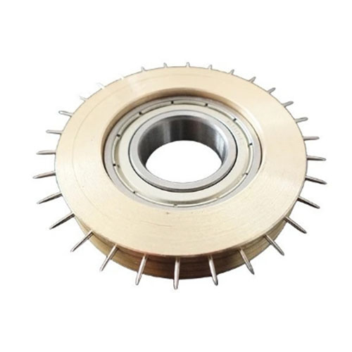
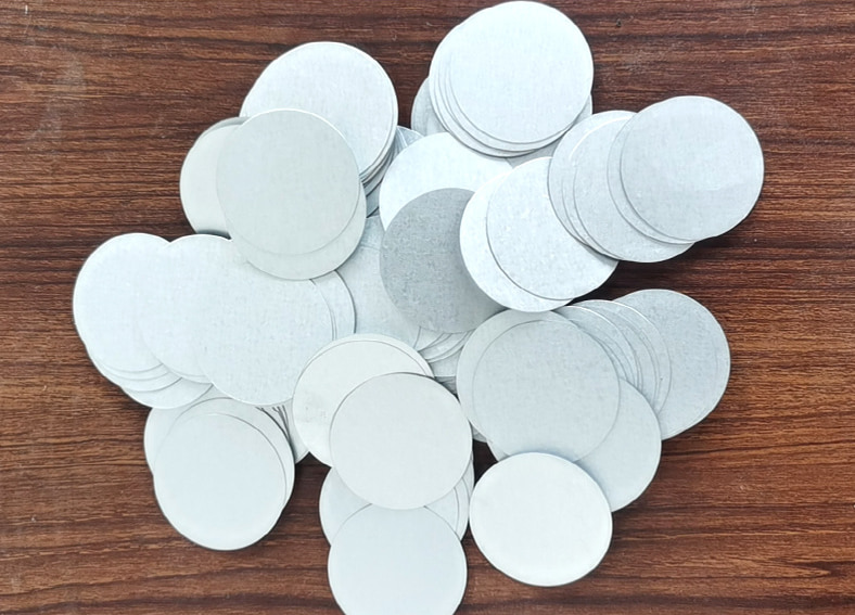
The Galvanized Roofing Tin Caps is a mechanical seal between two objects, usually used to reduce the pressure between two objects, corrosion and natural thermal expansion and contraction of the pipeline leakage. Since there are no possible defects on the machined surface, irregularities can be filled with tin caps.


The Galvanized Roofing Tin Caps is a special metal material, mainly composed of aluminum and zinc, with strong corrosion resistance and mechanical strength, so it is widely used in the field of construction in exterior wall decoration, roofing and interior decoration.


The use of Tin Roofing Caps in conjunction with roofing nails provides an additional layer of protection and stability. The Tin Roofing Caps extend the nail's surface area, enabling it to hold shingles and underlayment in place. Roofing Tin Caps are made from galvanized material, offering excellent holding power and stability when used in conjunction with roofing nails. The efficient, round design of the tin roofing caps is Miami Dade approved.


Electrical Galvanized Roofing Tin Caps


Our Galvanized Roofing Tin Caps are made of high quality aluminized zinc sheets. 


Surface Treatment : Electrical Galvanized


The size is complete and can be customized.


If you are interested in our products, welcome to contact us: frank@hfsunwell.com, and we will serve you wholeheartedly. 


READ MORE >

New Products 28 Degree Wire Strip Nails

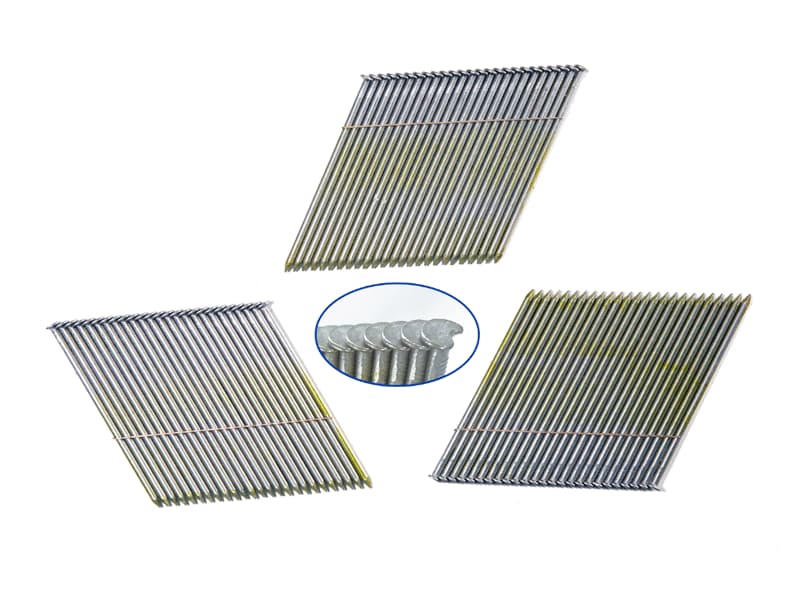
28 Degree Collated Framing Nails are commonly used in pneumatic nail guns for framing applications. These nails are typically made of steel wire and hold them together in a collated manner. The 28-degree angle refers to the angle between the nail shaft and the nail head, which allows for better access to tight corners and angles when framing.


SUNWELL strip nails are designed and manufactured in four different forms and are generally identified by what holds the nails together plastic, paper, wire, or adhesive. Adhesive collation is used on finish nails and brads for trim and fine woodwork.  The plastic, wire, and paper collated nails are used for general framing and crating applications.


Our 28 Degree Wire Strip Framing Nails are made of high-quality wire.


Nail Shank Available: Smooth, Ring, Screw


Finishing Available: Bright Finish, Hot Dip Galvanized (HDG), Electro Galvanized (EG), Stainless Steel (SS).


Coating Available: Yellow, Red, Blue, Sliver


Nail Head Available: Clipped Head, Offset Round Head.


The size is complete and can be customized.


If you are interested in our products, welcome to contact us, and we will serve you wholeheartedly.

READ MORE >

Step-by-Step Guide to Using a Roofing Coil Nailer

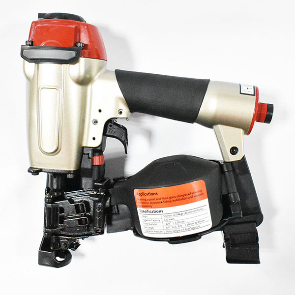
This blog provides a detailed guide for safely and effectively using a roofing coil nailer. It starts with essential safety tips, emphasizing the importance of wearing appropriate personal protective equipment, such as safety glasses and ear protection.


Roofing Nailer Gun AirClaw CRN45A Roof Coil Nail Gun

1.  Before operation

(1) Wear safety glasses or goggles

(2) Do not connect the air supply

(3) Inspect screw tightness

(4) Check operation of the contact arm & trigger if moving smoothly

(5) Connect the air supply

(6) Check the air-leakage.(the tool must not have the air-leakage.)

(7) Hold the tool with finger-off the trigger, then push the contact arm against the work-pieces.(the tool must not operate.)

(8) Hold the tool with contact arm free from work-piece and pull the trigger.(the tool must not operate.)


2.  Operation

Keep hands and body away from the discharge outlet when driving the fasteners because of dangerous of hitting the hands or body by mistake.


Nail loading

(1) Disconnect the air hose.

(2) Press LATCH to open DOOR, then open MAGAZINE COVER.

(3) Adjust the height of NAIL SUPPORT according to nails length.

(4) Fix the first nail in the groove on FEED PAWL.

(5) Close MAGAZINE COVER, close DOOR.

(6) Connect the air hose.


Test operation

(1) Adjust the air pressure at 70psi. (5 bar) and connect the air supply.

(2) Without touching the trigger, depress the contact arm against the work-piece. Pull the trigger.(the tool must fire the fastener.)

(3) With the tool off the work-piece, pull the trigger. Then depress the contact arm against the work-piece.(the tool must fire the fastener.)

(4) Adjust the air pressure as much as the lowest possible according to the diameters and length of fastener and the hardness of work-piece.


READ MORE >

Electric Floor Heating Installation

Installing electric underfloor heating is a process that involves several steps and precautions to ensure the efficiency and safety of the system. Here are some key precautions for installing electric underfloor heating:


Preliminary preparation: Before installing electric underfloor heating, a needs assessment is necessary to clarify the area of ​​the house, the rooms used, and the desired underfloor heating effect in order to select the appropriate electric underfloor heating system. At the same time, choosing the right materials and equipment is also essential to ensure the stability and efficiency of the system. 1


Floor preparation: Make sure the floor is flat, dry, and free of debris. If the floor is uneven, leveling is required. The flatness of the floor is the basis for ensuring uniform heat dissipation of the electric underfloor heating system.


Installation of insulation layer and reflective mat: The insulation layer is used to prevent heat from going downward and improve heating efficiency. The reflective mat is used to reflect heat and further improve the heating efficiency. The installation of these two layers of materials must be uniform and tight to avoid gaps.


‌Install the electric heating cable or electric heating mat: According to the design plan, lay the electric heating cable or electric heating mat on the floor. The cables should be evenly distributed to avoid overlapping or crossing. The electric heating mat should be installed according to the requirements of the instructions, and the joints should be insulated.


‌Install the thermostat‌: The thermostat is an important part of the electric floor heating system, which is used to adjust and control the indoor temperature. The thermostat should be installed in places where the air temperature is uniform, and should not be installed in places where the temperature changes greatly, such as corners, doors and windows. ‌2


‌Lay a waterproof layer‌: Lay a waterproof layer on the electric heating cable or electric heating mat to prevent moisture from entering the electric floor heating system and protect the safety and service life of the electric heating cable or mat.


‌System test‌: Before laying the surface layer, the electric floor heating system must be tested to ensure that the system is fault-free before the next construction step can be carried out.


‌Power supply requirements and safety‌: Ensure that the power supply is safe and reliable, and comply with relevant electrical safety standards. The power cord should be of appropriate specifications and avoid series connection. ‌ 


‌Floor material selection‌: Select floor materials with good thermal conductivity to ensure that heat can be evenly distributed throughout the floor. Avoid using moisture-proof mat, because moisture-proof mat is heat-insulating and will affect heat transfer. ‌ 


‌Professional installation‌: The installation of the electric floor heating system must be carried out by professionals to ensure the normal operation and safe use of the system.  


Maintenance: After the electric floor heating is installed, the system must be cleaned and maintained regularly to ensure its normal operation and extend its service life.


By following these precautions, the safe, stable and efficient operation of the electric floor heating system can be ensured, providing users with a comfortable heating experience.

READ MORE >

The Ultimate Solution for Static Control


The Ultimate Solution for Static Control


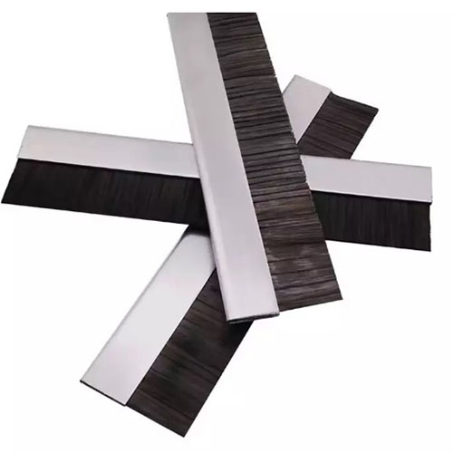
In a world where precision and reliability are paramount, carbon fiber brushes emerge as a game-changer in the fight against static electricity. Designed for high-performance applications, these brushes are a specialized type of anti-static brushes, offering unique benefits that set them apart in various industries.


Key Features

Exceptional Conductivity: The unique structure of carbon fibers ensures superior electrical conductivity, making these anti-static brushes ideal for safely dissipating static charges in sensitive environments.

Lightweight and Durable: Carbon fiber is not only lightweight but also incredibly strong, providing a brush that can withstand rigorous use without compromising performance.

Versatile Applications: From electronics to cleanrooms, these anti-static brushes are perfect for environments where static control is critical, such as semiconductor manufacturing or delicate assembly processes.

Low Maintenance: Carbon fiber brushes are easy to clean and maintain, ensuring long-term effectiveness without the need for frequent replacements.


Applications

Electronics Manufacturing: Prevents static damage to sensitive components during assembly.

Cleanrooms: Ideal for use in sterile environments to control static without introducing contaminants.

Automotive Industry: Essential for the assembly of electronic components, where static can cause malfunctions.


Our Carbon Fiber Brushes embody innovation and efficiency, providing industries with a reliable tool for static control. By integrating these anti-static brushes into your processes, you not only enhance operational safety but also promote a culture of quality and precision.

READ MORE >

Discover the Benefits of Outside Curve Brushes


Discover the Benefits of Outside Curve Brushes


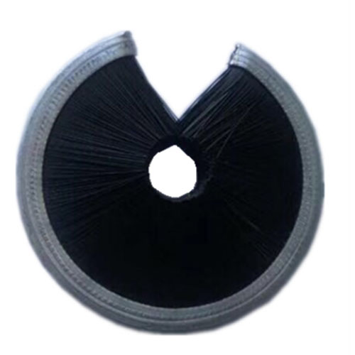
In the realm of industrial brushes, outside curve brushes stand out as a specialized tool designed for unique applications that require precision and efficiency. These brushes are engineered to tackle tasks that involve curved surfaces, making them indispensable in various industries.


Key Features of Outside Curve Brushes

Ergonomic Design: The curved shape of these brushes allows for better contact with rounded surfaces, ensuring thorough cleaning and finishing. This ergonomic design minimizes user fatigue while maximizing effectiveness.

Versatile Bristle Options: Available in various bristle materials—such as nylon, steel, and natural fibers—outside curve brushes can be customized to suit specific cleaning or polishing needs across different materials.

High Durability: Crafted to withstand rigorous industrial environments, these brushes are built to last, offering consistent performance even under heavy use.

Efficient Cleaning: The design of outside curve brushes enables them to effectively clean hard-to-reach areas and intricate contours, making them ideal for complex machinery and components.


Applications of Outside Curve Brushes

Automotive Industry: Used for cleaning and finishing curved components, these brushes ensure that every part meets strict quality standards, enhancing overall product reliability.

Aerospace Manufacturing: In aerospace applications, where precision is critical, outside curve brushes help maintain the integrity of complex surfaces and reduce the risk of imperfections.

Metal Fabrication: Ideal for deburring and polishing, these brushes are essential in the metalworking industry, ensuring smooth finishes on curved edges and surfaces.

Mold and Die Cleaning: Effective for cleaning molds and dies, the curved design allows for thorough cleaning of intricate details, extending the lifespan of these critical tools.


Why Choose Outside Curve Brushes?

Choosing outside curve brushes means investing in a tool that enhances efficiency and effectiveness in specialized cleaning and finishing tasks. Their unique design and robust construction make them the perfect choice for industries that demand precision and reliability.

By integrating these brushes into your processes, you can ensure that your products maintain the highest quality standards while streamlining operations.

READ MORE >

\"The Unsung Heroes of Industry Perforated Rollers\


The Unsung Heroes of Industry: Perforated Rollers


In the vast landscape of manufacturing tools and equipment, certain components often work tirelessly behind the scenes, yet remain largely unrecognized. Among these unsung heroes are high density perforated rollers—a vital yet often overlooked element in various industrial processes.

Why Perforated Rollers Matter

Facilitating Fluid Dynamics: The intricate design of perforated rollers allows for seamless fluid movement, whether it's air, water, or chemicals. This capability is essential in applications like textile dyeing and food processing, where the proper distribution of materials is key to quality.

Enhancing Operational Efficiency: By enabling faster drying and cooling processes, these rollers minimize production time and maximize output. Their ability to handle high volumes with minimal downtime makes them an invaluable asset in busy production lines, especially when integrated with equipment like a industrial punching machine for precise material preparation.


Real-World Impact

Consider a textile manufacturer that relies on consistent dye application. The integration of perforated rollers can significantly enhance color uniformity, leading to higher customer satisfaction and reduced waste. Similarly, in the food industry, these rollers ensure that products maintain their integrity during drying and cooling, preventing spoilage and preserving flavor.


Versatile Applications

Textile Manufacturing: For dye distribution, where precision is crucial.

Food Processing: In drying and cooling processes to maintain quality.

Packaging: Facilitating the movement and separation of products efficiently.

Recycling: Effectively separating materials in waste management processes.

Punching Operations: Working in conjunction with a punching machine to prepare materials for further processing.


A Worthy Investment

While perforated rollers may not be the most glamorous tools in the manufacturing world, their impact is profound. By enhancing quality and efficiency, they play a crucial role in driving success across various industries. Investing in high-quality perforated rollers is an investment in operational excellence and product quality.

READ MORE >

904L tube sheets and 904L flanges

904L alloy steel has the following characteristics:

904L is a highly alloyed austenitic stainless steel with low carbon content. This steel is designed for environments with harsh corrosion conditions. Initially, this alloy was developed for corrosion resistance in dilute sulfuric acid. This feature has been proven to be very successful through years of practical application. 904L has been standardized in many countries and has been approved for use in the manufacture of pressure vessels. 904L alloy, like other commonly used CrNi austenitic steels, has good resistance to pitting and crevice corrosion, high resistance to stress corrosion cracking, good resistance to intergranular corrosion, good processability, and weldability. The maximum heating temperature during hot forging can reach 1180 degrees Celsius, and the minimum stop forging temperature is not less than 900 degrees Celsius. This steel can be hot formed at 1000-1150 degrees Celsius. The heat treatment process of this steel is 1100-1150 degrees Celsius, and it is rapidly cooled after heating. Although this steel can be welded using universal welding processes, the most appropriate welding methods are manual arc welding and tungsten inert gas arc welding. When using manual arc welding to weld plates with a diameter not exceeding 6mm, the diameter of the welding rod shall not exceed 2.5mm; When the plate thickness is greater than 6 millimeters, the diameter of the welding rod is less than 3.2 millimeters. When heat treatment is required after welding, it can be done by heating at 1075-1125 degrees Celsius and then rapidly cooling. When using tungsten inert gas arc welding, the filler metal can be used with the same welding rod. After welding, the weld seam must be pickled and passivated.


904L metallographic structure

904L is a completely austenitic structure, and compared to austenitic stainless steels with high molybdenum content, 904L is not sensitive to the precipitation of ferrite and alpha phase.


Corrosion resistance of 904L

Due to the low carbon content of 904L (maximum 0.020%), there will be no carbide precipitation under general heat treatment and welding conditions. This eliminates the risk of intergranular corrosion that occurs after general heat treatment and welding. Due to its high chromium nickel molybdenum content and the addition of copper, 904L can be passivated even in reducing environments such as sulfuric acid and formic acid. The high nickel content results in a lower corrosion rate even in the active state. In pure sulfuric acid with a concentration range of 0-98%, the usage temperature of 904L can reach up to 40 degrees Celsius. In pure phosphoric acid with a concentration range of 0-85%, its corrosion resistance is very good. Impurities have a strong impact on the corrosion resistance of industrial phosphoric acid produced by wet process technology. Among all types of phosphoric acid, 904L has better corrosion resistance than ordinary stainless steel. In highly oxidizing nitric acid, 904L has lower corrosion resistance compared to high alloyed steel grades without molybdenum. In hydrochloric acid, the use of 904L is limited to lower concentrations of 1-2%. Within this concentration range. The corrosion resistance of 904L is better than that of conventional stainless steel. 904L steel has high resistance to pitting corrosion. Its resistance to crevice corrosion is also very good in chloride solutions. The high nickel content of 904L reduces the corrosion rate in pits and crevices. Ordinary austenitic stainless steel may be sensitive to stress corrosion in an environment rich in chloride at temperatures above 60 degrees Celsius. By increasing the nickel content of the stainless steel, this sensitization can be reduced. Due to its high nickel content, 904L exhibits high resistance to stress corrosion cracking in chloride solutions, concentrated hydroxide solutions, and environments rich in hydrogen sulfide.


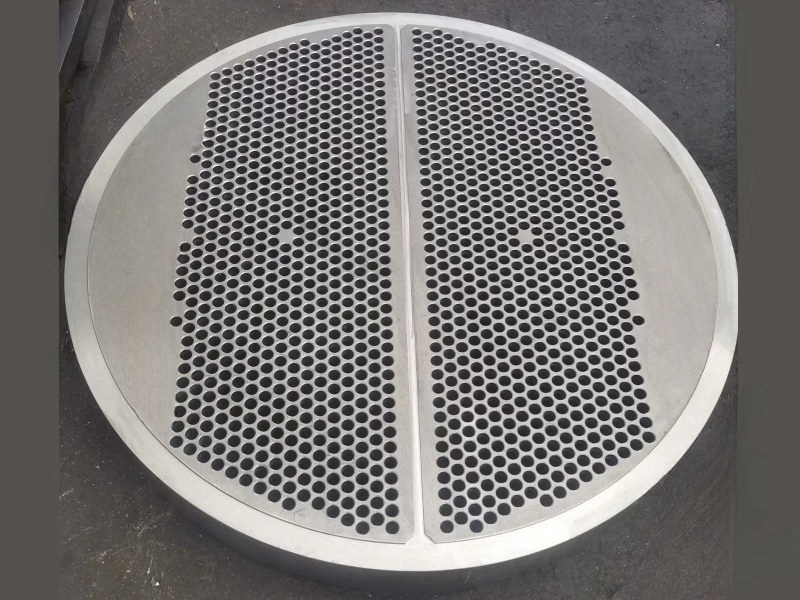
904L Tube sheet 

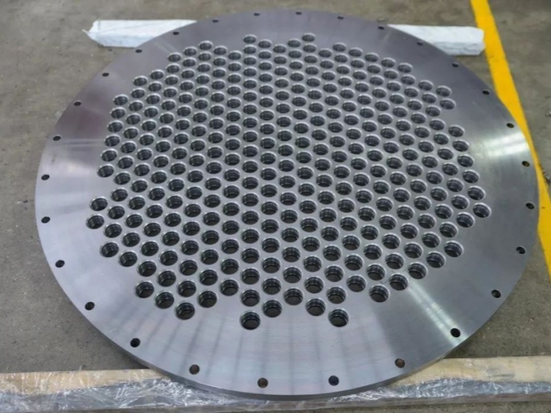
A 904L tube sheet is a component used in various industrial applications particularly in heat exchangers and condensers. The 904L stainless steel tube sheet is specifically chosen for its superior resistance to aggressive environments, such as those containing sulfuric acid, phosphoric acid, and chloride solutions. It offers exceptional resistance to pitting, crevice corrosion, and stress corrosion cracking, making it highly suitable for applications in the chemical, petrochemical, and offshore industries. The use of 904L stainless steel tube sheets ensures the long-term reliability and performance of heat transfer equipment. Its corrosion resistance properties allow for extended service life and reduced maintenance requirements, resulting in cost savings and enhanced operational efficiency. Choose 904L tube sheets for superior corrosion resistance and reliable performance in demanding environments. Experience the benefits of this high-quality stainless steel alloy for your heat exchangers and condensers.

stainless steel tube sheet


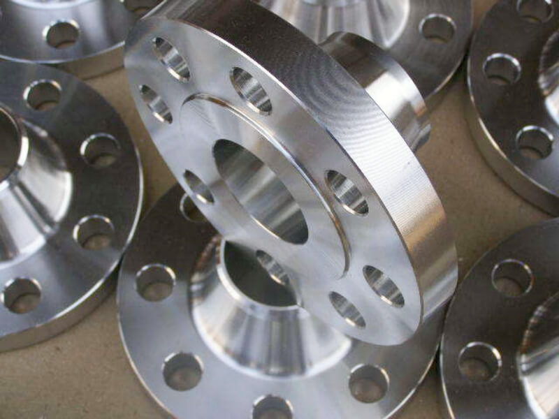
904L flange

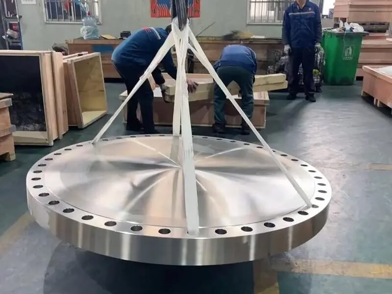
904L flanges are commonly used in industries such as chemical processing, petrochemical, pharmaceutical, and offshore applications. Their resistance to corrosion makes them suitable for handling corrosive fluids and gases. Additionally, 904L flanges offer excellent strength, durability, and weldability, making them a reliable choice for critical applications. The use of 904L flanges can help ensure the integrity and longevity of piping systems by providing a robust and corrosion-resistant connection. They are available in various types, including slip-on, weld neck, blind, and threaded flanges, to suit different installation requirements. In summary, 904L flanges are specifically made from 904L stainless steel, which offers superior corrosion resistance in demanding environments. Their use can enhance the reliability and performance of piping systems, making them ideal for applications where corrosion resistance is paramount.

Pipe flange


904L application areas:

904L alloy is a versatile material that can be applied in many industrial fields:

1. Petroleum and petrochemical equipment, such as reactors in petrochemical equipment.

2. Storage and transportation equipment for sulfuric acid, such as heat exchangers.

3. The flue gas desulfurization device in power plants is mainly used in the tower body, flue, door panels, internal components, spray systems, etc. of the absorption tower.

4. Scrubbers and fans in organic acid treatment systems.


Similar grades

GB/T UNS AISI/ASTM ID W.Nr

00Cr20Ni25Mo4.5Cu

N08904 904L F904L 1.4539


904L chemical composition

C

Si Mn P S Cr Ni Mo Cu Fe

0.02

1 2 0.045 0.035 19-23 23-28 4-5 1-2  


Mechanical properties

Tensile strength Yield Strength Elongation Density Melting point
RmN/mm Rp0.2N/mm A5% 8.0g/cm3 1300-1390℃


Wuxi Changrun has provided high-quality tube sheets, nozzles, flanges, and customized forgings for heat exchangers, boilers, pressure vessels, etc. to many well-known petrochemical enterprises at home and abroad. Our customers include PetroChina, Sinopec, Chevron, Bayer, Shell, BASF, etc. Send your drawings to sales@wuxichangrun.com We will provide you with the best quotation and the highest quality products.


READ MORE >

ASTM A182 F5 flange

The characteristics of ASTM A182 F5 flange

The ASTM A182 F5 Flange is constructed of chromium molybdenum steel. It is lightweight and has a high rupture resistance. It is also resistant to hydrogen attack and cracking caused by sulfide corrosion. The material Alloy Steel ASTM A182 F5 Flanges is widely used in the petrochemical and power generation industries. These flanges are widely used in a variety of industries such as power generation, gas processing, oil drilling, pharmaceuticals, and seawater equipment.


Slip-on and threaded ASTM A182 F5 Flanges are also available. Flanges made of alloy steel grade F5 and alloy steel grade F9 are suitable for high temperatures and pressure. These flanges are built to withstand high pressures and are made from high-quality raw materials. As a result, they are the preferred option for any industrial project.

weld neck flange


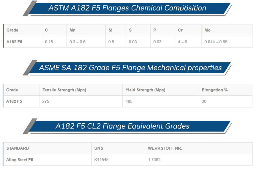
ASTM A182 F5 Flanges chemical composition and mechanical properties

The ASTM A182 F5 specification covers requirements for F5 alloy steel forgings and forged products such as chemical composition, mechanical properties, heat treatment, and other supplementary requirements.


ASTM A182 F5 flange usage range

ASTM A182 F5 Flanges are available in nominal bore sizes ranging from 1/2-inch to 36-inch. They come in a variety of pressure ratings and are typically used in smaller piping systems. They are also used in high-risk environments where welding connections would be hazardous. Look no further than our ASTM A182 F5 Flange if you need high-quality flanges.


ASTM A182 F5 Weld-neck Flanges are used in industrial, high-pressure applications such as condensers, boilers, evaporators, heat exchangers, and so on. Also, Wuxi changrun offer a wide range of Alloy Steel ASTM A182 F5 Flanges such as ASTM A182 F5 Slip On Flanges, Alloy Steel F5 Weld Neck Flanges, F5 Alloy Steel Socket Weld Flanges, A182 F5 Alloy Steel Blind Flanges, Alloy Steel F5 Orifice Flanges, A182 Alloy Steel F5 Spectacle Blind Flanges, A182 F5 Screwed / Threaded Flanges, Alloy Steel F5 Reducing Flanges, ASTM A182 F5 Alloy Steel Ring Type Joint Flanges (RTJ), etc. 

flange manufacturer


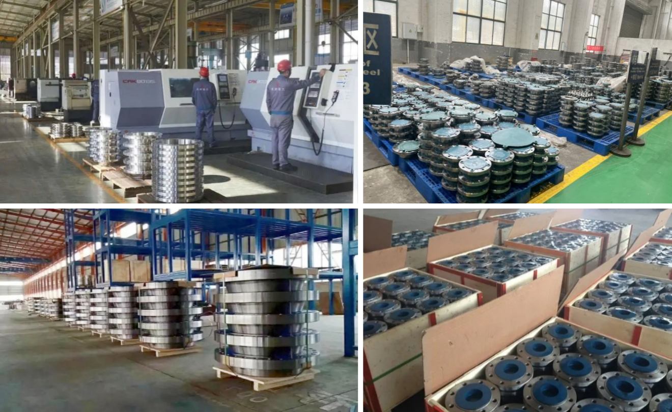
Wuxi Changrun has provided high-quality tube sheets, nozzles, flanges, and customized forgings for heat exchangers, boilers, pressure vessels, etc. to many well-known petrochemical enterprises at home and abroad. Our customers include PetroChina, Sinopec, Chevron, Bayer, Shell, BASF, etc. Send your drawings to sales@wuxichangrun.com. We will provide you with the best quotation and the highest quality products.

forged tube sheet


READ MORE >

Introduction to Ten Types of Shell and Tube Heat Exchangers

Shell and tube heat exchangers account for approximately 90% of the total amount of heat exchangers used in industry, making them the most widely used type of heat exchanger.


The typical structural forms of shell and tube heat exchangers include fixed tube sheet heat exchangers, U tube heat exchangers, floating head heat exchangers, stuffing box heat exchanger, kettle reboilers, double tube sheet heat exchangers, brace tube sheet heat exchangers, flexible tube sheet heat exchangers, and Spiral Wounded Heat Exchangers.


1. Fixed tube sheet heat exchanger

The fixed tube sheet heat exchanger (Figure 1) is a fixed connection (integral or clamped) between the two end tube sheets and the shell.

This is the most widely used type of heat exchanger. The two ends of the heat exchange tube are fixed on the tube sheet, which is welded to the shell.

fixed tube sheet heat exchanger


Fixed tube sheet heat exchangers are suitable for various occasions:

1)In situations where the temperature difference between the metal on the tube and shell side is not very large and the pressure is high. When the temperature difference between the metal on the tube and shell side is large, the pressure cannot be too high because the large temperature difference will inevitably increase the expansion joint, which has poor pressure resistance.

2) Due to the inability of the shell side to be mechanically cleaned, it is required that the shell side medium be clean; Or in situations where scaling may occur but can be removed through chemical cleaning.


Advantages:

1) It has a simple structure, less use of forgings, and low manufacturing cost.

2) The tube side can be divided into various forms of multiple passes, and the shell side can also be divided into two passes.

3) The heat transfer area is 20% to 30% larger than that of a floating head heat exchanger.

4) The bypass leakage is relatively small.


Disadvantages:

1) Not suitable for situations where there is a significant difference in thermal expansion deformation between heat exchange tubes and shell side cylinders, as temperature difference stress can easily occur between the tube sheet and tube end, leading to damage.

2) After the corrosion of the pipe, it leads to the scrapping of the shell, and the lifespan of the shell components is determined by the lifespan of the pipe, so the equipment lifespan is relatively low.

3) The shell cannot be cleaned and inspection is difficult.


2. U-shaped tube heat exchanger

The U-shaped tube heat exchanger (Figure 2) is a heat exchange tube with two ends fixed on the same tube plate, which is fixedly connected to the shell (integral or clamped).

fixed tube sheet heat exchanger


U-shaped tube heat exchangers can be used in the following situations

1) The flow in the pipeline is clean fluid.

2) The pressure in the pipeline is particularly high.

3) In situations where there is a large temperature difference between the metal on the tube and shell sides, and fixed tube plate heat exchangers cannot even meet the requirements with expansion joints.


Advantages:

1) The free floating at the end of the U-shaped heat exchange tube solves the temperature difference stress and can be used for two media with large temperature differences. The temperature difference between the metal on the tube and shell side is not limited.

2) The tube bundle can be pulled out to facilitate frequent cleaning of the outer wall of the heat exchange tube.

3) With only one tube plate and a small number of flanges, the structure is simple and there are few leakage points, resulting in a lower cost.

4) It can work under high temperature and high pressure, and is generally suitable for t ≤ 500 ℃ and p ≤ 10MPa.

5) Can be used in situations where shell side scaling is relatively severe.


Disadvantages:

1) When the flow rate in the pipe is too high, it will cause serious erosion on the U-shaped bend section, affecting its service life. Especially for pipes with low R, the flow rate inside the pipe should be controlled.

2) The pipeline is not suitable for situations with heavy scaling.

3) Due to the limitation of u-tube Rmim and wide separation distance, the number of tubes in the fixed tube sheet heat exchanger is slightly less.

4) When the heat exchange tube leaks, except for the outer U-shaped tube, it cannot be replaced and can only be blocked.

5) The central part of the tube bundle has large pores, and the fluid is prone to short circuits, which affects the heat transfer effect. Therefore, partitions should be added to reduce short circuits.

6) Due to the large dead zone, it is only suitable for the inner guide tube.

7) The number of heat exchange tubes arranged on the tube plate is relatively small.

8) The U-shaped bending section of the outermost pipe, due to its large unsupported span, should cause fluid induced vibration problems.

9) When there are requirements for stress corrosion, careful consideration should be given.


3. Floating head heat exchanger

The floating head heat exchanger (Figure 3) is a clamped type where one end of the tube sheet is fixedly connected to the shell, while the other end of the floating head tube sheet (including the floating head cover, backing device, etc.) floats freely inside the tube box. Therefore, there is no need to consider temperature difference stress, as there is a large temperature difference between the metal walls of the tube and shell sides.
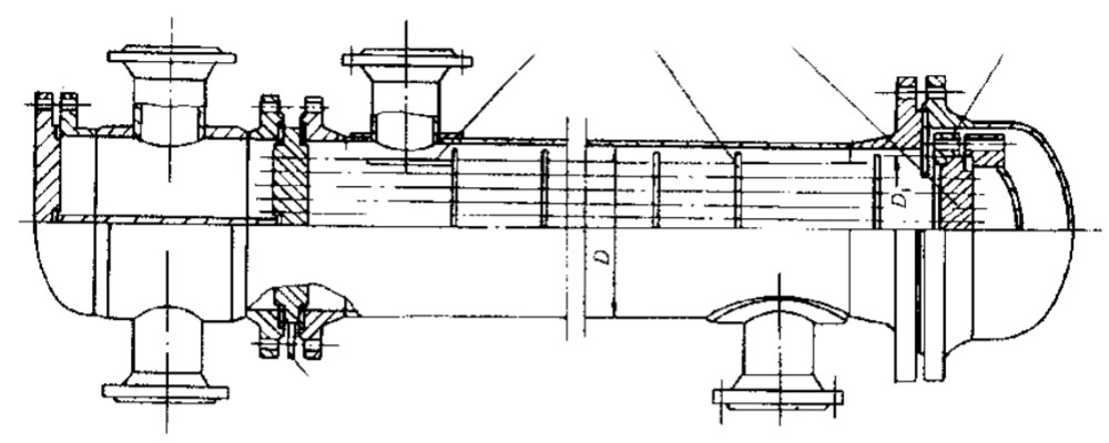
Floating head heat exchanger


Advantages:

1) The tube bundle can be pulled out for easy cleaning of the tube and shell side.

2) The shell wall and tube wall are not limited by temperature difference.

3) It can work under high temperature and high pressure, generally t ≤ 450 ℃ and p ≤ 6.4MPa.

4) Can be used in situations with severe scaling.

5) Can be used in pipeline corrosion scenarios.


 Disadvantages:

1) It is difficult to take measures when leakage occurs during the operation of the floating head sealing surface inside the shell side medium.

2) Complex structure, high metal material consumption, and high cost.

3) The floating head structure is complex and affects the number of pipes arranged.

4) The pressure test fixture used during pressure testing is complex.

5) Metal materials consume a large amount and have a 20% higher cost.


stuffing box heat exchanger

One end of the tube sheet is fixedly connected to the shell (clamp type), while the other end of the tube sheet floats freely inside the packing box.


The tube bundle can be extended and can be used for two media with a large temperature difference. The structure is also simpler than that of a floating head, making it easier to manufacture and more cost-effective than a floating head heat exchanger. Because the tube bundle can be pulled out, it is easy to maintain and clean. Suitable for use in media with severe corrosion.


4.1 Outside packed heat exchanger (Figure 4)

Suitable for equipment with a diameter below DN700mm, and the operating pressure and temperature should not be too high. It is generally used in situations where p ≤ 2.0MPa.

Outside packed heat exchanger


4.2 Sliding tube sheet packing box heat exchanger

At the sealing point on the inner side of the packing, there will still be a flow phenomenon etween the medium on the tube and shell side, which is not suitable for situations where the medium on the tube and shell side is not allowed to mix.
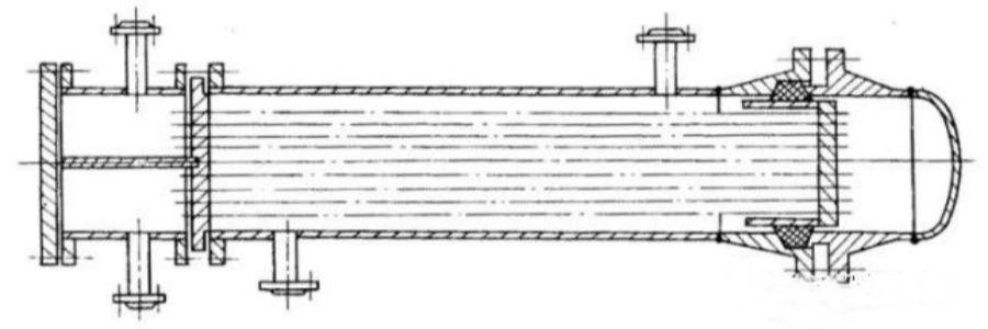
 

4.2.1 Single stuffing box heat exchanger (Figure 5)

At the sealing point on the inner side of the packing, there will still be a flow phenomenon between the medium on the tube and shell side, which is not suitable for situations where the medium on the tube and shell side is not allowed to mix.

Single stuffing box heat exchanger


4.2.2 Double stuffing box heat exchanger (Figure 6)

The structure is mainly sealed with the inner ring to prevent internal and external leakage, while the outer ring is used as an auxiliary seal to prevent external leakage. A leakage outlet pipe is set between the inner and outer sealing rings to connect with the low-pressure vent main. This structure can be used for medium with moderate harm, explosive and other media.
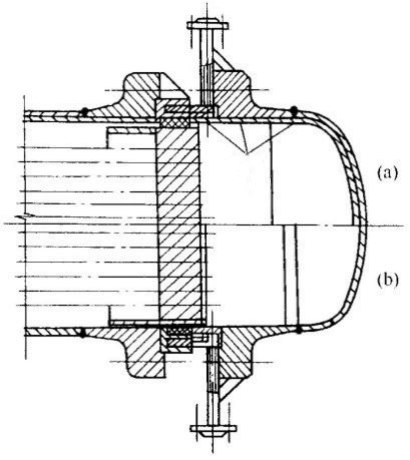
Double stuffing box heat exchanger


5. Kettle reboiler 

The kettle reboiler (Figure 7) is a fixed connection (clamp type) between one end of the tube sheet and the shell, and the other end is a U-shaped or floating head tube bundle. The shell side is a single (or double) inclined cone shell with evaporation space, so the temperature and pressure on the tube side are higher than those on the shell side. Generally, the shell side medium is heated by the tube side medium. P ≤ 6.4 MPa.
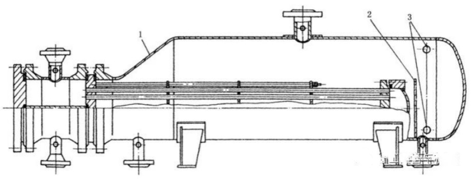
Kettle reboiler

Advantages:

1) Suitable for bottom reboilers and side line siphon reboilers.

2) Save over 25% of equipment weight.

3) Good corrosion resistance.

4) It has a self-cleaning effect. In situations where there is a large temperature difference between the tube and shell side.

5) The total heat transfer coefficient has increased by more than 40%.

6) In situations with high vaporization rates (30-80%).

7) In situations where the liquid phase of the reboiled process medium is used as a product or requires high separation requirements.

8) Good corrosion resistance.


Disadvantages:

1) On heavy oil equipment, such as residual oil and crude oil equipment, there is no application history.

2) Not suitable for environments with wet hydrogen sulfide.


6.Double tube sheet heat exchanger

The double tube sheet heat exchanger (Figure 8) has two tube sheets on each side, and one end of the heat exchange tube is connected to both tube sheets simultaneously. Mainly used for mixing the medium between the tube side and shell side, which will result in serious consequences. But manufacturing is difficult; High design requirements.
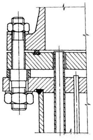
Double tube sheet heat exchanger


1) Corrosion prevention: Mixing the two media of the tube side and shell side can cause severe corrosion.

2) Labor protection: One route is a highly toxic medium, and infiltration into the other route can cause extensive system pollution.

3) In terms of safety, mixing the medium on the tube side and shell side can cause combustion or explosion.

4) Equipment contamination: Mixing of tube side and shell side media can cause polymerization or the formation of resin like substances.

5) Catalyst poisoning: The addition of another medium can cause changes in catalyst performance or chemical reactions.

6) Reduction reaction: When the medium on the tube side and shell side is mixed, it causes the chemical reaction to terminate or limit.

7) Product impurity: When the medium in the tube and shell is mixed, it can cause product contamination or a decrease in product quality.


6.1 Double tube sheet fixed tube sheet heat exchanger (Figure 9)

Double tube sheet fixed tube sheet heat exchanger

6.2 Double tube plate U-tube heat exchanger (Figure 10)

Double tube plate U-tube heat exchanger

6.3 Double tube U-tube kettle reboiler (Figure 11)
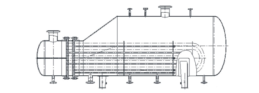
Double tube U-tube kettle reboiler


7.Pulling tube sheet heat exchanger

The pull-up tube sheet heat exchanger (Figure 12) has a thinner tube plate thickness, usually between 12 and 18mm.

Pulling tube sheet heat exchanger


7.1 The structural types include:

(1) Face to face (Germany): The tube sheet is welded onto the sealing surface of the equipment flange (Figure 12a).

(2) Inlaid type (former Soviet Union) ГОСТ Standard): The tube sheet is welded to the flat surface of the equipment flange sealing surface (Figure 12b).

(3) Corner welding (formerly developed by Shanghai Pharmaceutical Design Institute): The tube sheet is welded to the shell (Figure 12c).


7.2 Scope of application:

1) Design pressure: The tube side and shell side shall not exceed 1.0 MPa respectively;

2) Temperature range: The design temperature range for the tube side and shell side is from 0 ℃ to 300 ℃; The average wall temperature difference between the heat exchange tube and the shell shall not exceed 30 ℃;

3) Diameter range: The inner diameter of the shell shall not exceed 1200mm;

4) Heat exchange tube length: not exceeding 6000mm.

5) Heat exchange tubes should be made of light tubes and have a linear expansion coefficient close to that of the shell material (the difference in values between the two should not exceed 10%).

7.3. Expansion joints should not be installed.


8. Flexible tube sheet heat exchanger

Suitable for horizontal shell and tube residual (waste) heat boilers with gas as the medium on the tube side and saturated water vapor generated on the shell side.

The connection between Type I tube sheet and shell (channel) (see Figure 13a) and the connection between Type II tube sheet and shell (channel) (see Figure 13b).
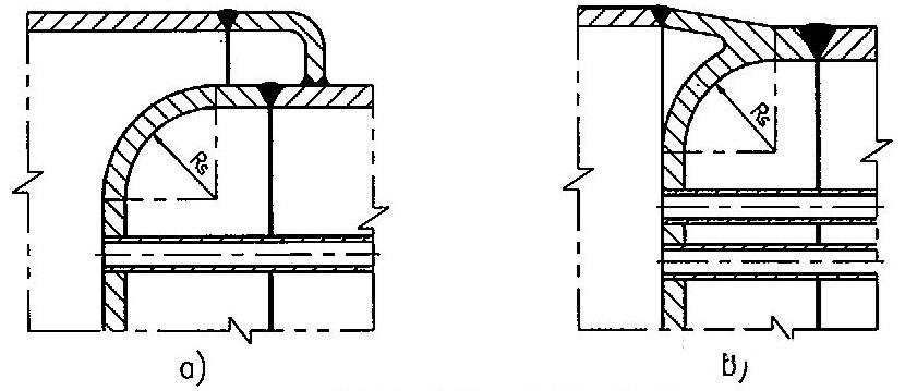
 

Applicable scope:

1) The design pressure of the tube side shall not exceed 1.0 MPa, the design pressure of the shell side shall not exceed 5.0 MPa, and the shell side pressure shall be greater than the tube side pressure;

(1) Type I is used for pipe design pressure less than or equal to 0.6MPa;

(2) Type II is used for piping design pressures less than or equal to 1.0 MPa.

2) The diameter of the shell and the length of the heat exchange tube are 2500mm and 7000mm, respectively.


9. Efficient spiral wounded tube heat exchanger

In order to save equipment investment, the maximum heat transfer area of heat exchange tubes is arranged within the limited shell volume of the heat exchanger, and the heat transfer efficiency is improved. Therefore, the shell and tube wound tube heat exchanger (Figure 16) has emerged. This type of heat exchanger is a multi-layer multi head stainless steel small diameter heat exchange tube wound and welded on the core rod, as shown in Figure 16.

Efficient spiral wounded tube heat exchanger


10. Austenitic stainless steel corrugated heat exchanger

1) Applicable scope:

(1) The design pressure shall not exceed 4.0MPa;

(2) The design temperature shall not exceed 300 ℃;

(3) The nominal diameter shall not exceed 2000mm;

(4) The nominal diameter shall not exceed 4000 times the product of the design pressure.

2) Inappropriate occasions

(1) Media with extreme or highly hazardous toxicity;

(2) Explosive media;

(3) In situations where there is a tendency towards stress corrosion.


Wuxi Changrun has provided high-quality tube sheets, nozzles, flanges, and customized forgings for heat exchangers, boilers, pressure vessels, etc. to many well-known petrochemical enterprises at home and abroad. Our customers include PetroChina, Sinopec, Chevron, Bayer, Shell, BASF, etc. Send your drawings to sales@wuxichangrun.com We will provide you with the best quotation and the highest quality products.
TUBE SHEET

READ MORE >